Radiation & Shielding
Magnetic Shielding
Positioning applications, which use linear motors to move a part under an e-beam,
as for example in
scanning
electron microscope (SEM) or in E-Beam
Lithography, often require shielding of the exposed magnet channels. Mu Metal is
commonly used for that purpose. Typical linear motor Rare Earth
magnets have flux density of about 0.7 Tesla at the surface of the magnet.
Some of
this flux is captured by the linear motor magnet channels ( back iron ).
At about 100 mm away from the the channel the flux density diminishes
exponentially to the order of a few Gauss. A DC magnetic flux density
of a few gauss may disturb the e-beam process, which is typically specified to
be protected on order of a mGauss. The effect of a steady flux
may be mapped out. However, if the flux density changes its magnitude during process, such as in
a moving compounded XY linear stages, shielding
may be required.
Design of magnetic shield is an iterative process, which is best being done by
experienced experts. The following are references
to two magnetic shield supplies.
|
|
|
Mu Metal
http://mumetal.co.uk
|
Netic and Co-Netic materials
http://www.magnetic-shield.com/products/alloys.html
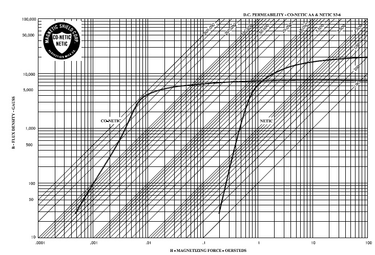
Our NETIC® and CO-NETIC® alloys, presented in this guide,
are proprietary materials developed by Magnetic Shield Corporation specifically
to provide effective magnetic shielding. Both are available in either foil or sheet form in a
convenient range of material thickness. The permeability
chart you see illustrates the unique properties of each material. In fields of low intensity,
CO-NETIC AA is used for its high initial permeability and
corresponding high attenuation characteristics. In fields of high intensity, NETIC S3-6 is
preferred because of its high magnetic saturation
characteristics. In some instances, combinations of the two materials may
be useful. NETIC material is always placed closest to the magnetic
field source. Many users explore the effects of magnetic shielding alloys
through use of our
Magnetic Shielding Lab Kit quickly prototyping
solutions to magnetic interference problems. The
sheet from these materials is preferred in areas of high magnetic force, where greater
alloy
thickness is necessary, or where substantial production tooling investment is justified.
Examples: Power supplies, CRTs, photomultiplier tubes, disk
drives, test chambers, and many electronic assemblies utilize cans, cylinders, boxes and
enclosures fabricated from flat sheet by heliarc or spot
welding. Foil may provide effective shieklding with minimum fabrication, avoiding expensive
tooling and extended production time. Examples:
Prototype and laboratory evaluation projects and production applications such as
shielding field-sensitive components, printed circuit boards,
instruments, signal leads and power cables.
|
Mu Metal Shielding examples of 0.7 Tesla
magnetic source at
the ceneter of 400 x 400mm space ( Optinet analysis samples ) |
|
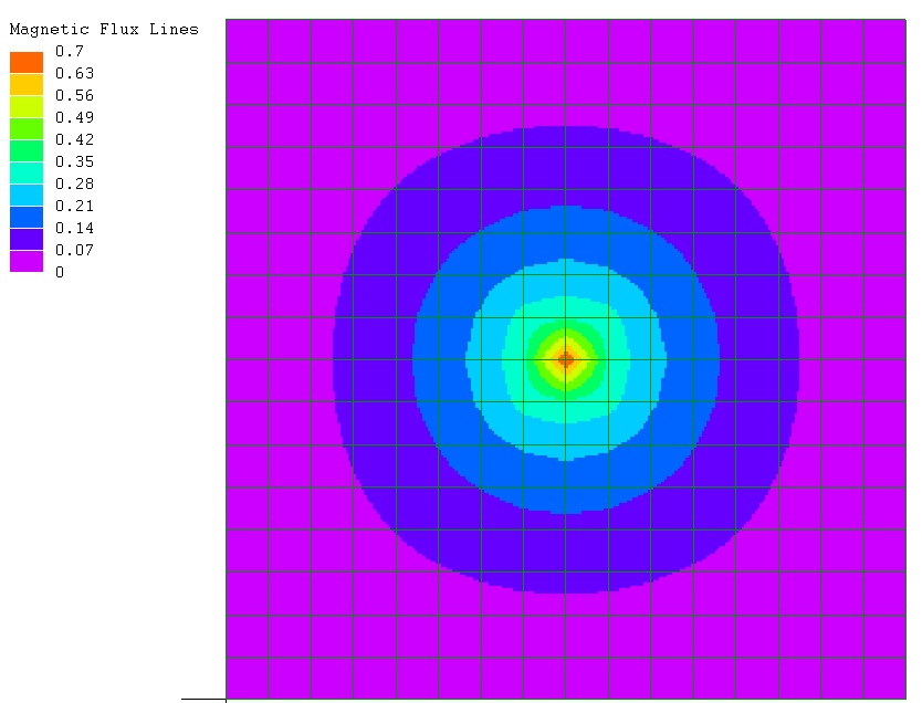
unshielded |
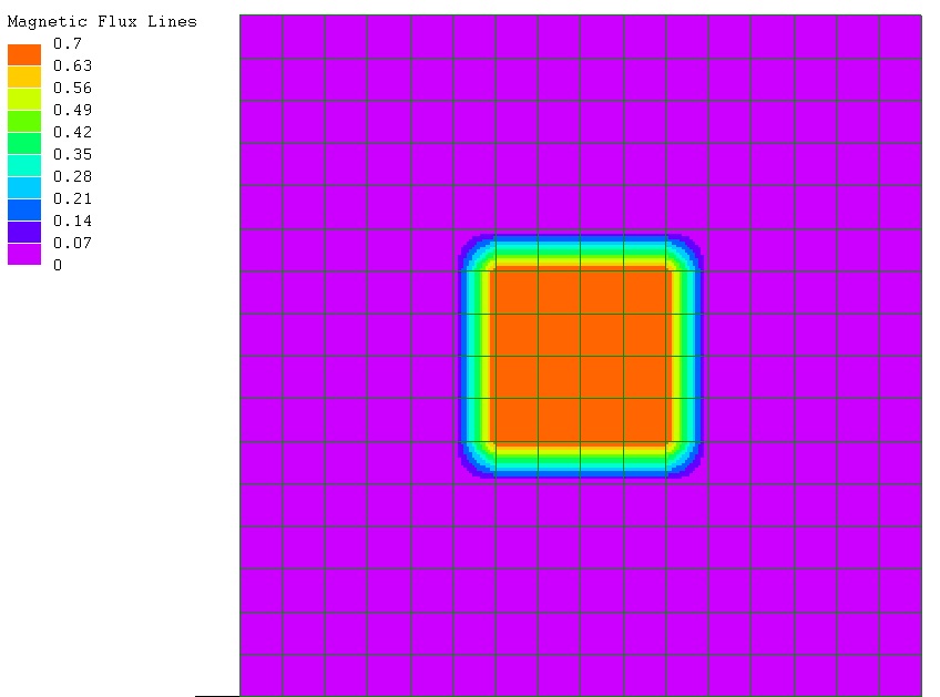
enclosed on four sides |
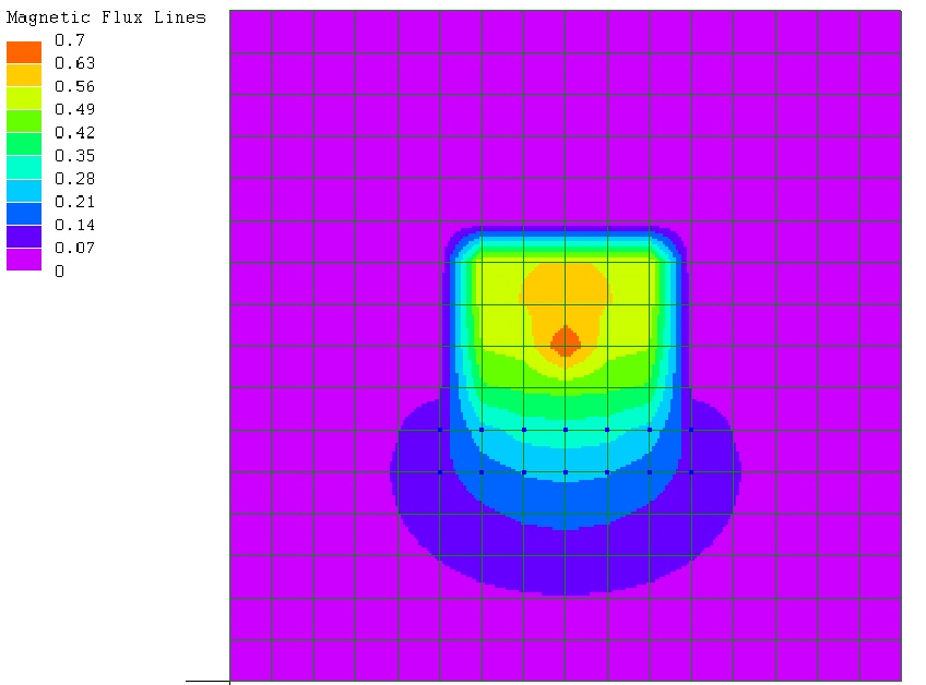
shielded on three sides
|
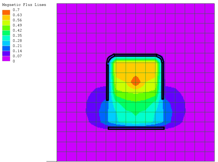
shielded on four sides with an opening |
|
|
EMI / RFI |
|
|
|
Design consideration for EMI / RFI shielding:
1. Separate signal cables from power cables
2. Consider linear servo amplifier ( rather than PWM ) in applications which
require very high smoothness of motion
3. Use common grounding ( including electrical cabinets, motors, encoders,
limits )
4. Use shielded cables
5. Use chokes
6. Use twised wires
7. Use metalized fabric outer surface for cables
8. Use ferrites
9. Transmit signals in differential form
10. Amplify signals to higher signal to noise ratio
11. Convert signal into currents for transmission
12. Convert signals to digital form
|
|
|
|
|
|
|
|
Ionizing Radiation |